Finally making some progress on this project. What I have learned is that you really need to know what your trying to achieve with discharging.
Mistake 1: I initially thought I was going to do a 40 amp load bank. My wallet, my packs and my knowledge on this topic said "Not so much".
Mistake 2: I tried to design a case out of lexan. After doing a test run with my Chargery 1500 power supply told me again "Not so much". You will need a bunch of cooling and the heat I was putting out will destroy the lexan over time. Nice thing about this power supply is that I have a screen that shows my data. I was at 25.4 volts at 24.4 amps draw. With that knowledge I will be able to calibrate the current sensor later.
Mistake 3: Heat sinks was the hardest part of this project. I spent almost 80% of my time on finding a heat sink. All of that was due to me thinking a cheap CPU style ones would be okay. Again "Not so much". What I did do however was take the fans off the heatsinks and now using them in my prototype build.
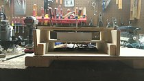
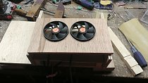
So after spending 2 hours making most of the lexan box I had to trash the idea. I switched over to some scrap wood i had around. I have a bunch of 1/2 inch sanded plywood. I also had a few pieces of dimensional pine left over from the solar box project. You will see the picks at the end of this post.
Let's look at the discharge portion of this. Do not base your current draw based on flight based current. This is where I got caught up and screwed. What I did do is look at the Amp hour of the packs. My packs are either 3 or 3.3 amp hour. I kept doing the math until I got down to around 7 minutes. This would be an ideal discharge rate. Which Ironically is how long my flights last on the 570. To simplify this all I did was doubled the amp hours at 30 minutes, then doubled the amp hour for 15 minutes and doubled it again for the 7.5 minute mark. This puts me around or about 20 to 25 amps. So thats my circuit, 25 amps and at 25 volts I would need 1 ohm of resistance. So 3 amp for one hour, 6 amps for 30 minutes, 12 amps for 15 minutes, 24 amps for 7.5 minutes.
The resistors drove me batty. I finally settled on a total of 1 ohm on the load bank. This gives me "Parity" between volts and amps. For ever volt you get 1 amp. I also wanted to stick with 5 resistors since that what most of these are made with. By no means are you stuck with just using 5. If I make a new one I will go to 6 ohm resistors and run 6 in parallel which nets me 1 ohm. Now you will need to watch the watts on the circuit. My resistors can handle 100 watts passively. I have 500 watts of total heat that I can handle without any additional cooling. Only problem is that this bank is going to produce 625ish watts of heat. So i need massive cooling. I hit a peak of 280 degrees F in about 2 minutes. After adding 3 fans, 2 under the load bank right at the resistors, and one on the heat sink. I was able to run around 180 degrees F at the high end or spikes. I was staying around 160 degrees F. I have added a fourth fan to the set up as you will see in the picks. I will give a list of the places I sourced my parts from in my final write up.
As of right now I am still waiting for a couple more parts. I still need a 30 amp relay, wire, binding posts, 4mm banana plugs, 10 turn potentiometer (ordered from china).My arduino and screen are on standby until I get the final assembly done. I still have to program the current sensor, the potentiometers and different screen layout. One thing I am tossing around is basing the shut down on a set current value or a voltage value. I am at parity so I am guessing I could shut it down based on amps. I also want to shut down if any one cells gets to low. So I still have so planning to do.


so the relay came in today. Did not realize how big it was going to be.


Mistake 1: I initially thought I was going to do a 40 amp load bank. My wallet, my packs and my knowledge on this topic said "Not so much".
Mistake 2: I tried to design a case out of lexan. After doing a test run with my Chargery 1500 power supply told me again "Not so much". You will need a bunch of cooling and the heat I was putting out will destroy the lexan over time. Nice thing about this power supply is that I have a screen that shows my data. I was at 25.4 volts at 24.4 amps draw. With that knowledge I will be able to calibrate the current sensor later.
Mistake 3: Heat sinks was the hardest part of this project. I spent almost 80% of my time on finding a heat sink. All of that was due to me thinking a cheap CPU style ones would be okay. Again "Not so much". What I did do however was take the fans off the heatsinks and now using them in my prototype build.
So after spending 2 hours making most of the lexan box I had to trash the idea. I switched over to some scrap wood i had around. I have a bunch of 1/2 inch sanded plywood. I also had a few pieces of dimensional pine left over from the solar box project. You will see the picks at the end of this post.
Let's look at the discharge portion of this. Do not base your current draw based on flight based current. This is where I got caught up and screwed. What I did do is look at the Amp hour of the packs. My packs are either 3 or 3.3 amp hour. I kept doing the math until I got down to around 7 minutes. This would be an ideal discharge rate. Which Ironically is how long my flights last on the 570. To simplify this all I did was doubled the amp hours at 30 minutes, then doubled the amp hour for 15 minutes and doubled it again for the 7.5 minute mark. This puts me around or about 20 to 25 amps. So thats my circuit, 25 amps and at 25 volts I would need 1 ohm of resistance. So 3 amp for one hour, 6 amps for 30 minutes, 12 amps for 15 minutes, 24 amps for 7.5 minutes.
The resistors drove me batty. I finally settled on a total of 1 ohm on the load bank. This gives me "Parity" between volts and amps. For ever volt you get 1 amp. I also wanted to stick with 5 resistors since that what most of these are made with. By no means are you stuck with just using 5. If I make a new one I will go to 6 ohm resistors and run 6 in parallel which nets me 1 ohm. Now you will need to watch the watts on the circuit. My resistors can handle 100 watts passively. I have 500 watts of total heat that I can handle without any additional cooling. Only problem is that this bank is going to produce 625ish watts of heat. So i need massive cooling. I hit a peak of 280 degrees F in about 2 minutes. After adding 3 fans, 2 under the load bank right at the resistors, and one on the heat sink. I was able to run around 180 degrees F at the high end or spikes. I was staying around 160 degrees F. I have added a fourth fan to the set up as you will see in the picks. I will give a list of the places I sourced my parts from in my final write up.
As of right now I am still waiting for a couple more parts. I still need a 30 amp relay, wire, binding posts, 4mm banana plugs, 10 turn potentiometer (ordered from china).My arduino and screen are on standby until I get the final assembly done. I still have to program the current sensor, the potentiometers and different screen layout. One thing I am tossing around is basing the shut down on a set current value or a voltage value. I am at parity so I am guessing I could shut it down based on amps. I also want to shut down if any one cells gets to low. So I still have so planning to do.
so the relay came in today. Did not realize how big it was going to be.