450 Need A Good Charger...

Tony

Staff member
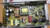
How you wire them is going to depend on how they are wired right now. The ones that I use need to have one of them with a "floated DC ground" so that if one or the other shorts out, it doesn't put 120vAC through the case and shock the crap out of you. That would be bad. So on the ones that I have, you have to float the DC ground on one of them. There are some others that don't need it, but I don't know what ones. Gaba is an electronic engineer and he also had help from another guy that knows these things very well and that is where he got his info from. I just took his writeup and made it into a video. As for your PSU, I have no idea.

And bump tags are just an RF tag (like a pike pass or whatever you have down there for toll roads) where you have a sensor and you put the tag on the battery. Once you program everything into the charger, you just put the battery up against the controller and it automatically knows what battery you are wanting to charge from the saved data. Takes a bit to set it up in the beginning, but works great at saving time after that. Like I said, I'm thinking about getting a PL charger just for that reason.
 

Rob Lancaster

Active Member
Yeah sounds good about what your say'n about the chassis ground, maybe GABA getting involved would be a great twist. My brother dabbles in the technician side of things too, so we can figure out what's what before I have a hair raising experience, ha! Whoa!!
He also said that using a switching power supply will reduce the cost immensely because they don't use large expensive transformers. They may be a bit noisy; but we're not running sensitive radio equipment where noise like that is a major problem.

Oh man! That bump tags stuff is the Jetson's already! Are we have'n fun yet?!!
 

murankar

Staff member
The bump controller is a unit that controls the PL series chargers. It controls up To 4 chargers at one time.

The idea behind the bump controller is a two fold idea. One; it allows you to program each pack or each set of packs one time and have access to those settings at the scan of a tag. Part 2 is the data collection of each tag. Each pack/tag entry will have its own "database" of data. Everything is saved from cycles to internal ir's. It tracks voltage during charge and discharge. You are also able to copy a tags settings to another for easy setup. It lastly allows you to connect to a phone so you can upload your data.


All of that to say is that it allows you to scan press start and wait for the cycle to end.
 

Tony

Staff member
Actually that is LMAO, and it stands for Laughing My Ass Off. You can also type : lmao: without the space to get this --> :lmao:
 

Tony

Staff member
You can also just click on the little smilie face at the top of the reply box to see all of them lol. I have a few on here. Some have told me that it is too many...
 

Rob Lancaster

Active Member
Wow! That Dual PowerLab 8T Charger is a killer setup!
Looks like you'll need to add two more power supplies to get the maximum power out it though.
Start'n to remind me of the old Omega station that used to operate up in the valley years ago.
I wonder if you can read the IR of the cells? I'll bet these chargers give the iCharger 406 DUO and the like some competition... Nice and nifty !
 

Rob Lancaster

Active Member
Excellent!! Them's nice chargers...………..
Oh hey just for the heck of it, I opened up my power supply to have a look at the DC grounds. Yup this unit has two on the PCB that connect to the box. I figure all these switching supplies are easy enough to modify if necessary. I'm just glad I know what to watch for.
Thanks buddy...
 

Tony

Staff member
Just note that not all PSU's need to be floated. They are all going to have a DC ground to the case, the key difference is if the AC side shorts out, will it try to go through the DC side to get to ground.
 

Rob Lancaster

Active Member
Yeah, that's the thing I need to work out. I'm still fuzzy on how that can happen. I need to figure out (with any power supply) how to know when and when not to modify. This is a head scratcher that's got me going... Probably loose sleep on it tonight, ha!
 

murankar

Staff member
Keep in mind most of the IR readings are done during the charge cycle. This may not be the most accurate reading you'll get. In fact to get the most accurate IR reading it has to be done in a super controlled environment.

For our purposes the charger will be just fine. For us its just a base line to see if our packs are toast or not.

For the PL series you'll need the full 36 volts to get the max output. If you run a dual PL 8 with 36v per charger you'll need two separate circuits in your house.
 

Rob Lancaster

Active Member
There's something else I didn't know! I do have one of those HK Mega 7 in 1 multimeters, it reads the IR when the battery is static but I really don't know how accurate it is.

Hey, about the two separate house circuits. I was thinking the same thing or I could just install a sub panel and dedicate the higher amps to a special outlet. All my small 15 amp wall circuits are already pushing it. Heck I could install that babee right next to the generator transfer switch I installed for all those power outages we have.

If anyone out there could help me better understand how a short in one power supply box could cause a shock hazard on the 2 or more of the surfaces of the boxes when touched; I'd really enjoy that... I'm still scratching my head on this riddle. I'm starting to think it has something to do with phase. I've heard of ground loops in the RF world but never really understood it. I want to know how it really functions...
 

Attachments

  • IMG_1646.JPG
    IMG_1646.JPG
    253.3 KB · Views: 3

Tony

Staff member
It's basically if/when the AC side shorts out, it can short through the DC ground. I'm not 100% sure how or where it does it, but that is the general path.
 

Eggy 71

Member
You need to remove one of the DC grounds because it would cause a short circuit if you try to connect the DC side in series. If the first PSU has one leg grounded then the output from the other leg is 12v. If you connect that to the other PSU + to - then there would be a difference in potential of 12v and short out. If you connect it + to + then the two open legs are the same potential and there is no current flow. By connecting the two PSU DC sides together electrically it is only one and there can only be one reference to ground potential in order for it to work.
 

Rob Lancaster

Active Member
Hi Eggy, thanks for jumping in..
Now I can see how a DC +12v potential can get on one of the boxes after drawing up what your trying to explain to me. Man I never thought about that before.
But I'm still thinking about what Tony said as well. Just one more thing, (Columbo said). How does AC current get on the boxes? (If one is not isolated).. And especially if one unit fails all together? How??
We're almost there; keep it coming!!
 

Eggy 71

Member
My background is in A/C and transformation. For that answer I'm just guessing. I don't know how the PSU converts A/C to D/C. The A/C sides of the PSUs are independent of each other so they both should have a ground connection to the case for safety in case the 120v from the wall came off and contacted the outer case. The D/C side needs one of the grounds removed in order to work. My guess is one of two:
1) the way the grounding is configured it's not possible to isolate A/C grounding from D/C grounding independently so both are removed in the conversion giving the possibility of the 120v from the wall causing the hazard or
2) the component that converts A/C to D/C has the ability to backfeed and 'pushes' 12v from the other PSU back through the converter and uses the ground connection as a lead to energize the outer case with 120v from the converter (I don't know it's proper name) .
Whatever it is as long as the two cases are contacting each other, they both are 'grounded' for shock/fire hazard. I'm running this setup powering a 306b and love it. If someone who is familiar on these has a different explanation please do. I'd like to know how they work.
 

Rob Lancaster

Active Member
A/C is converted to D/C by means of a full wave bridge rectifier. The rectifier can consist of four independent diode components or in most cases today, they are integrated into one small device. A/C goes in and pulsating D/C comes out.

Have a look at the pictures below. You got me thinking and I think I know how and where the A/C to D/C short can happen. First of all, a diode is a device that will pass voltage in one direction and block it coming back. There's two type of diode failures. One is an OPEN diode. (does not conduct in both directions).. The other is a shorted diode,(conducts in both directions)..

I think a shorted diode or diodes, will allow A/C to back feed through the ground pin of the rectifier and then on to the case if connected. At that point the breaker should trip or the fuse on the PCB should instantly blow. Anyway we are closer than ever. At least I know what to look for where as before I never gave it a second thought. In this case, a little info is a good thing... Watch out; A/C hurts..:dizzy: It's been awhile and I want to keep it that way.

I threw in a photo of the rectifier device in my 14v 30 amp power supply.
This thing is at least 10 years old and was caked with dust. The dust here in Hawaii sticks really bad because of the high humidity. I polished all the rust off of the screw terminals with a Dremel.. I used some electronics cleaner and a Q-Tip to clean all the crap out of it. On a micro level, that could cause a short as well on the D/C side. Darn this paradise! Oh,, sorry..... But really; THE HUMIDITY SUCKS OUT HERE!!!...… What's it tonight you ask? OOOOOHHH just 99% as the next hurricane moves closer; argggg!!

Ok everyone, let's see what else is to learned on this very interesting topic.
Keep it coming!!
There's more; I'm sure, let's keep digging so we can really understand what we're all dealing with. I figure, if I can absorb it, what the heck; right...
 

Attachments

  • IMG_1647.JPG
    IMG_1647.JPG
    162.7 KB · Views: 6
  • IMG_1648.JPG
    IMG_1648.JPG
    162.5 KB · Views: 6
  • IMG_1649.JPG
    IMG_1649.JPG
    253.6 KB · Views: 7
Top Bottom