
You are using an out of date browser. It may not display this or other websites correctly.
You should upgrade or use an alternative browser.
You should upgrade or use an alternative browser.
Misc. Wingtip Strobes
- Thread starter grumpy1
- Start date
RandyDSok
Well-Known Member
You're going to need something more complex than just a capacitor.
First a correction to what you wrote. Capacitors are not used inline, they are connected to a power source and a ground. When power is applied to them, they begin to store the voltage and "charge" up, when the power source is disconnected they release the voltage they've stored back to the circuit load. To say it another way, they buffer ( store ) the voltage until they are full and release it once the power source is stopped.
What you need is a timer circuit. I suspect a simple one using a 555 timer chip setup in astable mode would do what you are asking but it will take a bit of calculating to find out specifically what components you'd need. You'd need a couple of capacitors and a couple of resistors ( or better yet, two potentiometers so you can vary the time off and time on portions )... The values for the components you'll need will depend on the voltages and amperage of your circuit that is driving your strobes. If the circuit you are driving ( ie the strobes ) has a high amperage draw, you will likely need a relay also in order to switch things on/off so you don't overload the timer chip.
Here is an Instructable on using the 555 timer chip in 3 different modes ( including the astable mode )
555 Timer
Here is a video describing the basics of the 555 timer in it's various modes...
grumpy1
Active Member
Well...remember you ain't talkin to Nicola Telsa...in just a crusty ol' grumpy retired union pipe fitter..I had kinda hard time on something so simple as dot nav lights...resistors...voltage drop...mah..I'm process piping guy if I understood the terminology of the various components...would help greatly. I'm as lost as last years Easter egg
RandyDSok
Well-Known Member
Sorry it was a little ruff for ya... but it's a technical issue and required a technical answer if you had a chance of getting something you wanted. As far as electrical circuits go, it's a rather simple one but it does require a little understanding of the subject like many things.
grumpy1
Active Member
Ok...here we go, a review of what this ol dog has learned.looks like I need a srd-05vdc-sl-c relay...correct value uf cap. Next question. To decrease blink rate are uf values increased or decreased? Want strobes to blink 3 times and be off approximate the time of those 3 blinks. Am I going in the correction?
murankar
Staff member
So if I am thinking this right, the amount of blinks you get is directly related to the capacitor? if so the go with a smaller capacity cap. What size that is I dont know. You may need to view the data sheets of the components to find out what you need. Unless Randy has the knowledge already.
grumpy1
Active Member
That is true with cap value...wtih 6Hz strobes that blink rate is fine. My way of thinkin the cap is being used as a timer,the time the circuit is energized or switch closed. Next queston. One would think with 2 strobes in the line the cap value would have to be changed because the cap would discharge faster because it's powering 2 devices opposed to one. Is that correct?
RandyDSok
Well-Known Member
With it in astatic mode, the timing is controlled by both the capacitor and resistors. The capacitor will determine how quickly the circuit charges up but it's the resistors that will control how long the circuit is on and off. The timer is the 555 chip itself. When the circuit reaches 2/3'd of the source voltage the circuit goes on... when it drains back down to 1/3'd of the voltage it switches back off.
The 555 can work with anything from 4.5v up to 16v and can provide up to 7.5mA of power. If your strobe circuit have different needs ( voltage or amperage's ) a relay would be needed. I don't suspect a set of LED's would require more amperage than the output of the 555 can provide.
Besides the basics given above... I'm not going to be a lot more help. I can follow a set of instructions but I'm not into designing circuits. In short, I can follow a recipe but I wouldn't expect a lot more than that.
grumpy1
Active Member
Well...I got some 555's ,resistors an some various uf caps on the way..all the components should be here Friday. I've the caps covered I think..from 1 to 100 uf's in 10 different sizes. Now about the resistors you say they determine how long the circuit is on/off increase ohms to increase time on or what..both resistors , just one. I gonna make this work.
RandyDSok
Well-Known Member
You seem to ask questions when I either have a headache... or am up too late at night.... LMAO
The initial charge of the capacitor is the longest and only happens once. It is charging from zero volts up to 2/3's of the Vcc voltage ( input voltage value ). All consecutive times, the circuit is either charging up to the 2/3's voltage amount... or down to the 1/3'd voltage amount.
The next charge up is from 1/3 Vcc to the 2/3 Vcc voltage... that time is calculated by the amount of resistance of both resistors ( Ra and Rb ). The time that it takes to discharge down to the 1/3 Vcc voltage, is controlled by the value of just the second resistor Rb . Then everything repeats again and starts the cycle to charge back up from 1/3 Vcc to the 2/3 Vcc amount.
grumpy1
Active Member
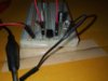
Well guys here's what I've come up with...played with just the cap to adjust the rate left the resistos the same value...1 10k an 1 100k what ya think settled with a 4.7uf cap at least it's 47 something ...what you think...now to transfer that to some kind of PC board...thats another challenge. Well tried to load video an send ...says file to large..give me some direction an try to send
grumpy1
Active Member
Man if feel like I'm being a pest asking all these questions. Anyway what kind of board do I need to get . I'm kinda like RDSOK ..Ican follow directions...before I wasn't even in the same boat....at least I'm in the boat now..barely at least you guys can see where the boats going...Im down here in the cargo hold...but in the boat tho...
Attachments
Tony
Staff member
You can do it a couple ways. First, you can get a bread board that has single through holes and you can use solder to bridge those holes to form the traces. The next way is to get a PCB that is solid copper and etch your own traces. Of course you would have to trace out your own traces first, but this is pretty easy with a black sharpie. The other way is to hit up this one company, design your board and have them make it. I'm sure they can make it quite small since we are talking very low current.
Here is an Instructibles tutorial of how to make your own - DIY Customized Circuit Board (PCB Making)
Here is the link to the place where you can design your own PCB and they will make it for you very cheap for the first order - PCB Prototype & PCB Fabrication Manufacturer - JLCPCB
And the single hole pcb's can be had on ebay or any electronic store (sans radioshack even though you can still order from them online lmao)
Hope this helps.